The applications of o-ring seals are classified according to relative movement. In the case of little or no movement, the application is static. In the case of reciprocating, rotating or oscillating motion, the o-ring application is dynamic.
Let us dive into the world of static sealing applications.
The static seal refers to the seal that does not move between the gland parts that are matched with it. There is no movement of the sealing surface between the seal and the gland.
1. Static axial seal
The static axial seal is a seal that is parallel to the centerline of the seal without movement and sealing. Sealing occurs at the top and bottom of the seal, which is the surface of the seal.
The face seal (Illustration 4.1) is a static axial seal. It is sealed on the sealed surface. Cut grooves on the flat surface (green). The o-ring (red) is placed in the groove, and the second plane compresses the o-ring (blue). This is a static application. The o-ring will not move after installation.
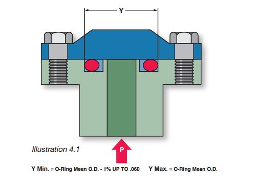
Illustration 4.1 shows a system with internal pressure. This system pressure will push the o-ring toward the outside diameter of the groove. The outer groove diameter should match the nominal O-ring outer diameter. This will minimize the displacement of the o-ring in the groove.
This outer groove diameter becomes the reference and the change of the inner groove diameter to obtain an appropriate groove width. On the contrary, when the system has external pressure, the o-ring will be pushed into the inner groove diameter. The inner groove diameter will become the reference, and the outer groove diameter will become the groove width.
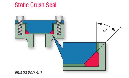
The crush seal (Illustration 4.4) is another static axial seal. The o-ring is pressed into a triangular groove. The volume of the o-ring seal is usually 90-95% of the volume of the seal ring. The o-ring is permanently deformed and is considered not to be reused.
The dovetail type provides a retention function in the end face seal gland. If the groove design in Illustration 4.5 is a standard surface seal, the o-ring will fall off as the valve circulates upwards. The dovetail leaves the o-shaped environmental protection in the groove. During installation, the o-ring is pressed into the dovetail, which may tear the o-ring. O-ring lubrication can reduce the chance of tearing.
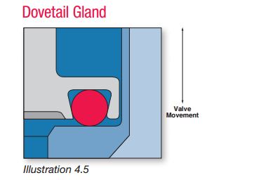
The dovetail groove results in a low volume occupancy rate. O-ring expansion may be caused by tolerances, extreme temperatures, chemical compatibility, etc., and does not work well in dovetail grooves.
2. Static radial seal
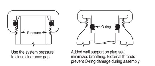
The sealing surface is perpendicular to the sealing centerline in the radial sealing direction. The sealing surface is on the inner and outer diameters, that is, the cross section of the o-ring. There are two variants of radial seals. One is the piston seal, the groove is on the piston, the illustration is to the right. The second is that the groove of the rod seal is boring, the illustration is to the left.
The axial sealing direction should be considered first, and then the radial sealing direction. The extrusion path and tolerance stack are easier to control in an axial setting. The groove depth is the only compression variable. The plates are assumed to be parallel and flat, with a small gap in between. In the radial configuration, there are tolerances for the bore diameter, groove diameter and piston or shaft diameter. The diameter gap between the hole and the shaft or piston is unavoidable. Poor tolerances will cause this gap to grow, possibly allowing the o-ring to squeeze through it. Excessive hole and slot diameter tolerances will affect compression.